Categories
- Conventional fire alarm systems
- Wireless Fire Alarm System
- LPCB addressable fire alarm
- Addressable fire alarm system
- Gas detection alarm system
- Electrical Fire Monitoring
- Fire Alarm Fire Extinguishing
- Fire Alarm gas fire-extinguish
- Commercial Burglar Alarm System
- Security Service Equipment
- Commercial security solutions
- Industry Security Equipment
Manufacturers
Languages
Important Links
- addressable fire alarm bus
- Addressable Fire Alarm System
- addressable fire alarm system loop
- Security Alarm Systems Affiliate program
- bus short circuit isolator
- overview of automatic fire alarm systems
- fire alarm input module
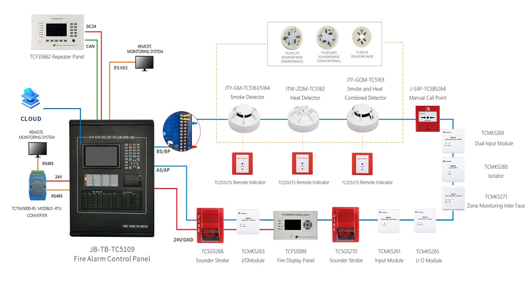
- TC5109 Fire Alarm Controller Function
- Tiancheng Fire Alarm Manufacturer
- Fire Alarm Programming
- Vedard Security Alarm Products
- Debugging Of Automatic Fire Alarm And Linkage Control System
- Point-type infrared flame detector
- Fire Fighting Control Ways
Debugging Of Automatic Fire Alarm And Linkage Control System
How to debug the automatic fire alarm and linkage fire fighting security system after wiring?
1. Understand the project overview
Before debugging the project, it is necessary to have a general understanding of the project and have a clear idea in mind.
2. Prepare for debugging
With knowledge of the engineering site, it is necessary to organize the tools, accessories, and products or components to be replaced during debugging and maintenance. It is important to prepare well. If you are well prepared, you will be at ease with your work. On the contrary, if you are not well prepared, you will appear powerless in your work. So it is important to pay attention to the preparation work before debugging.
3. Debugging equipment
The engineering debugging process is shown in the attached table
1) After the contract is signed, technical personnel will conduct a technical briefing to the construction party, so that they can understand our company's equipment and some issues that should be noted in the construction wiring. If the construction party is unclear, our technical personnel need to explain clearly.
2) Provide Party A with a linkage logic relationship table and request Party A to provide the linkage logic relationship. Based on this relationship, our technical personnel will write a linkage relationship table and store it in the computer for input into the host during project debugging.
3) Provide Party A with an address code table and request Party A to provide the address code of external fire protection equipment. Based on this code, our technical personnel will write an "English annotation" table and store it in the computer for input into the host during project debugging.
4) After receiving the commissioning notice, the commissioning personnel shall rush to the site in time, and first check the external lines to check whether there is any error in wiring, whether there is short circuit between lines, and whether there is open circuit in the lines. The resistance to ground of the circuit measured with a shake meter should be greater than 20M Ω. For a fully loaded circuit, the resistance between the circuit buses measured with the resistance range of the multimeter should be around 5K. If it is not normal, notify the construction party to correct it in a timely manner. If everything is normal on the external line, it can be connected to the host.
5) Before connecting to the host through an external line, it is necessary to run a short circuit test on the host. Connect the 220V host fire protection dedicated power supply. Run and test the host without any load (including return lines, dedicated control lines, and all external lines). Is the recording function functioning properly. If there is a malfunction, it should be resolved immediately to ensure the normal operation of the host.
6) After connecting the external line to the host, setting up the host mainly includes the following process:
a. Set the networking mode of the local machine
When the local machine is set to "multi master mode", it can receive alarm information, fault information, and linkage information from other hosts in the network; When the local machine is set to "slave mode", it does not receive alarm information, fault information, or linkage information from other hosts in the network. When the local machine is set to "multi master mode", it can receive alarm information, fault information, and linkage information from other hosts in the network through settings. If all controllers that make up the network are set to "multi master mode", then this network is a peer-to-peer network structure.
b. Set local address
When used for networking multiple controllers, the local network address ranges from 1 to 31. For a single controller, the local address can be set to any number from 1 to 31. If the local address is not set, the system will prompt "input error, please re-enter" when writing linkage programming operations.
c. System configuration
According to the specific configuration, set the "number of circuit boards", "number of bus control panels", "number of dedicated line control panels", and "number of gas fire extinguishing control panels".
The range of bus control disks is 1 to 32; The number of dedicated control panels ranges from 1 to 8; The range of gas fire extinguishing control panels is 1 to 8.
d. Clear operation
Clear the registration information, linkage programming, and bus control panel address correspondence in the system.
7) Register circuit components
Before registering the circuit components, test that the background current of the circuit is not greater than 18mA. If it is normal, perform automatic registration, and then use the "Circuit Status Signal Browse" function to check if the circuit components are normal. The normal state signal value of each circuit component should be 5-8mA, and the state signal value during alarm should be 17-24mA. If two circuit components are duplicated, their state signal values will be superimposed. After automatic registration, the sensitivity of cigarette butts and thermometers will default to level 2 sensitivity. Check if the registered number is equal to the actual number, detect faulty devices, fire alarm devices, and devices that are not registered until all devices are operating normally. Executing automatic registration will not clear the annotation information and linkage programming of circuit components.
8) Input English comments and linkage programming
Input the pre written linkage logic relationship and device English annotations into the host. Check its correctness.
Required hardware equipment:
One computer installed with WIN11 or above operating system, English annotations, and linkage programming software
⑵ One serial port cable, connected as shown in Figure 2.
The English annotations include: circuit components and dedicated line components.
9) Set the correspondence between bus control panels
According to the linkage requirements, match the registered TCMK3202 module with the corresponding control points on the bus control panel.
10) Fault detection of dedicated control panel
Set whether to detect startup module faults, stop module faults, and answer startup module faults in the 'Direct Control Fault Detection Settings'. The group without TCMK3207 module should be set to '0'. When any group of the dedicated control panel reports a fault, the host linkage fault light will light up and a fault sound will sound, and the corresponding fault information will be displayed on the LCD screen. When the system is equipped with a dedicated control panel, the linkage control mode of the system is controlled by the "manual" and "automatic" locks on the No.1 dedicated control panel. Each group of dedicated control panels only has one start answer signal. There are two types of answer modes: active and passive. 1. Active mode: The 220V AC voltage answer terminal of the external device is connected to the device answer terminals' AS1 'and' AS2 'of the TC3207 module, and the answer light on the TCMK3207 module lights up when answering. 2. Passive mode: When the S - and G of the TCMK3207 module are short circuited, answer when the 'S+' and 'S -' are short circuited.
The output 24V of the dedicated control panel should use a linked power supply instead of the main power supply to avoid burning the main unit when connected incorrectly. When automatically allowed, when the action state maintenance time in the linkage programming of the corresponding linkage module of the dedicated control panel is set to '∞', it is a continuous output. It can also be set as a jog signal, and the output should stop after a certain number of seconds. When external devices can protect themselves, it is recommended to use jog mode. When manually allowed, manual startup is allowed, and the startup method is the same as the linkage programming method in automatic permission.
11) Set up fault detection for gas fire extinguishing control panel
Set whether to detect gas fire extinguishing equipment faults in the "Direct Control Fault Detection Settings".
12) Linkage logic relationship detection
Test whether the edited linkage logic relationship is linked according to the pre designed requirements. If it is incorrect, manually adjust it. If the first party requests to change the original linkage relationship during testing, the responsible person of the first party needs to sign and confirm before our debugging personnel can make changes, that is, to clarify responsibilities.
13) CRT fire display system
Install the FireCRT alarm display system software into the microcomputer and connect it to the RS232 interface of the controller host through a serial port cable (as shown in Figure 2).
Based on the fire plan provided by Party A, use CAD2002 software to draw the floor plan for each floor, and then transfer it to CRT software. Then, according to the fire plan, add the corresponding fire equipment at the corresponding position in the floor plan of CRT. For specific operation methods, please refer to the "FireCRT Alarm Display System User Manual".
4. System trial operation
When all the functions of the system (including alarms, linkage, etc.) are debugged and the host can work normally, the system should be allowed to run for a period of time. During this period, all loads must be carried. And set a password that does not allow other personnel to operate.
5. Testing of alarm and linkage functions
If there are no issues during the trial operation of the system, a comprehensive testing of the system can be conducted with the engineering company, including alarm, linkage, and related equipment, to test the coordinated action of the entire fire protection system.
6. Acceptance project
After testing without any issues, the fire engineering company will coordinate with relevant departments and submit a request for acceptance to the fire department. After receiving the fire inspection notice, we will cooperate with Party A and the construction party to complete the fire inspection.
7. Transfer equipment and train operators
After the system acceptance is completed, we will be responsible for training the operators of relevant departments, including equipment operation methods, handling methods for various situations, and handling methods for some problems that arise during equipment operation. In order for operators to operate the controller correctly and handle various situations in a timely manner, if they cannot be resolved, they can provide feedback to us in a timely manner and we will send technical personnel to handle it. Finally, the engineering company hands over the fire-fighting equipment to the user.
8. Keep good records
Corresponding work records should be kept for the above tasks, so that there will be records available for future visits, maintenance, and repairs.
More Information
Bestsellers
- High Sensibility smoke and heat...
- Break beam solar power wireless...
- Audio visual alarm conventional...
- Conventional fire alarm sounder...
- Conventional manual call point ...
- Horn strobe flash and sounder fire...
- PIR detector solar power wireless...
- Wireless infrared beam security...
- 2 fire zone Mini conventional fire...
Specials [more]
8 Beam Sensor Wireless Solar power Perimeter Security Equipment
Save: 6% off

Aspirating Smoke Detector Suction-type Fire Detection
Save: 14% off