Categories
- Conventional fire alarm systems
- Wireless Fire Alarm System
- LPCB addressable fire alarm
- Gas detection alarm system
- Electrical Fire Monitoring
- Addressable fire alarm system
- Fire Alarm Fire Extinguishing
- Fire Alarm gas fire-extinguish
- Commercial Burglar Alarm System
- Security Service Equipment
- Commercial security solutions
- Industry Security Equipment
Manufacturers
Languages
Fire Alarm gas fire-extinguish
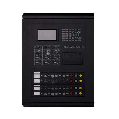
Fire alarm and gas fire-extinguishing control panel
TC5105 fire alarm and gas fire-extinguish
Product Description
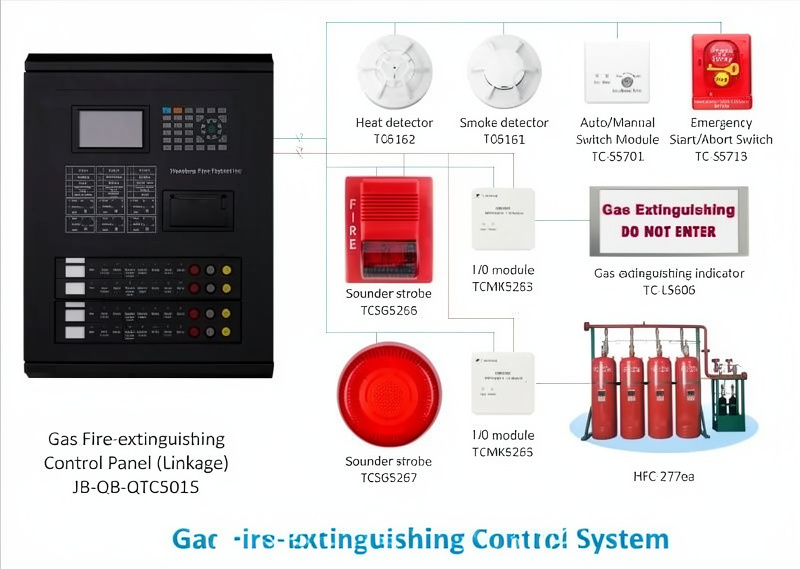
Gas fire-extinguishing system is mainly used in environments that are not suitable for setting water fire extinguishing system and other fire extinguishing systems, such as computer room, important library archives, mobile communication base station (room), UPS room, battery room, general diesel generator room, etc.
* Color menu display
* Max 4 fire protection zones and 1 Fire Alarm loop
* Max 6 direct control points
* Networking function
* Built-in printer
* Wall-mounted structure ,compact and exquisite
* Connection with field devices through loop control
* The system is a combination of alarm, linkage and gas fire-extinguishing
* Devices can be connected include smoke detector, heat detector, flame detector, MCP, emergency start/abort button, sounder strobe, gas spray indicator, auto/manual switch module and I/O module
Compatible components can be found at fire extinguisher panel
 Main power supply: AC220V(3A), Voltage range: +10%~-15%
Battery: DC24V (10A), 12V/12AH sealed acid battery *2
LCD screen: 4 inch color LCD screen, resolution:480*272
Capacity: 255~510 points /1~2 loops /2~4 zones
Operating environment: Temperature: 0~+40°C, relative humidity<=95% non-condensing
Dimension: 385mm*134mm*510mm
Communication interface: RS485, CAN, USB
L, N, PE: AC 220V terminals and AC grounding terminals. L+, L-: non polarized alarm loop signal bus system terminals. Qn+, Qn-: non-polarized gas loop signal bus system interface, n: gas zone, No.1~4.NO, CM, NC: fire alarm volt-free output interface (NO: volt-free open junction, CM: volt-free sharing junction, NC: volt-free closed junction). SG+, SG-: sounder strobe control output terminals (volt control point, active output DC24V, output DC24V stopped after manually stopped or reset).
A2, B2: RS485 terminals connecting figure display in fire protection control room, A2 for A point of485, B2 for B point of485.
Al, BI: RS485 terminals, Al for A point of485, BI for B point of 485 (optional). Qn, Gn, Hn: direct control interface of threc-wire system, n for loop No. for three-wire system,No. 1-6. CH, CL: polarized Can bus system of control panel networking.
JP2: pin set at the peripheral networking terminal on loop mainboard. Short cut piece jumps to ON when the panel is connected to peripheral network terminal,24V, GND: linkage power output terminals. Encode corresponding detectors and modules of gas fire-extinguishing.
Main power supply: AC220V(3A), Voltage range: +10%~-15%
Battery: DC24V (10A), 12V/12AH sealed acid battery *2
LCD screen: 4 inch color LCD screen, resolution:480*272
Capacity: 255~510 points /1~2 loops /2~4 zones
Operating environment: Temperature: 0~+40°C, relative humidity<=95% non-condensing
Dimension: 385mm*134mm*510mm
Communication interface: RS485, CAN, USB
L, N, PE: AC 220V terminals and AC grounding terminals. L+, L-: non polarized alarm loop signal bus system terminals. Qn+, Qn-: non-polarized gas loop signal bus system interface, n: gas zone, No.1~4.NO, CM, NC: fire alarm volt-free output interface (NO: volt-free open junction, CM: volt-free sharing junction, NC: volt-free closed junction). SG+, SG-: sounder strobe control output terminals (volt control point, active output DC24V, output DC24V stopped after manually stopped or reset).
A2, B2: RS485 terminals connecting figure display in fire protection control room, A2 for A point of485, B2 for B point of485.
Al, BI: RS485 terminals, Al for A point of485, BI for B point of 485 (optional). Qn, Gn, Hn: direct control interface of threc-wire system, n for loop No. for three-wire system,No. 1-6. CH, CL: polarized Can bus system of control panel networking.
JP2: pin set at the peripheral networking terminal on loop mainboard. Short cut piece jumps to ON when the panel is connected to peripheral network terminal,24V, GND: linkage power output terminals. Encode corresponding detectors and modules of gas fire-extinguishing.
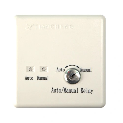
Auto/Manual Switch Module for Gas Fire-extinguish
Product Description Conversion Between manual operation mode and automatic operation mode Installed at the entrance of the protected area In manual state,systems will not linkage In automatic state,systems will linkage Compatible with JB-QB-QTC5015 Gas Fire-Extinguishing Control Panel Operating voltage: Signal bus voltage: bus 24V, range 16V~28V Operating current: <=1mA Coding method: Electronic coding, coding range can be set between 39~40 Weight: about 110g Operating environment: Temperature 0~+40°C, relative humidity<=95% non-condensing Dimension: 86mm*86mm*38mm Mounting hole distance: 60mm Material and color of enclosure: ABS, Milky white
$18.00
Gas Extinguishing Indicator
TC-L5719 Gas Extinguishing Indicator generally installed outside the gas extinguishing spraying area. When the gas extinguishing is carried out, the gas spraying indicator lights up, showing "Do not enter after deflation" to prevent people from entering by mistake and causing injuries. Non-polarized bus two-wire,ultra-low power consumption design,no need of DC 24V power supply Electronic code can be written in advance by encoder. BV copper conductor with cross-sectional area≥1.5mm2 shall be selected for DC 24V Operating Volate DC24V Operating Current ≤250mA Operating environment Temperature: -10~+55℃; relative humidity≤95%, non-condensing Coding method Electronic coding, coding range: can be set between 31~38 Dimension 86mm*86mm*38mm Mounting hole distance 60mm
$13.50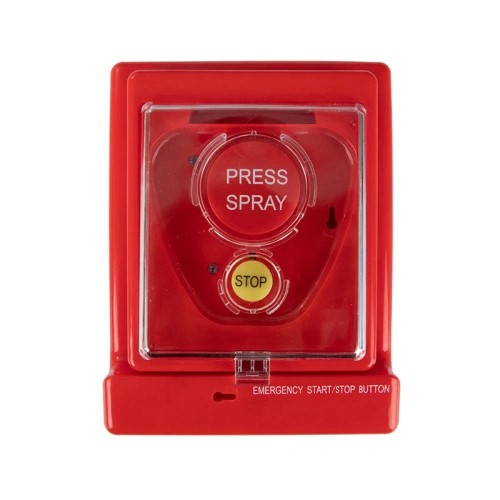
Emergency Start/Abort Button
TC-S5713 Emergency Start/Abort Button Features of Emergency Start/Abort Button Non-polarized two bus system Installed at the entrance of the protected area When fire occurs,press emergency start/abortswitch Special key resettable L1,L2:non-polarized two bus input RVS twisted pair is selected for L1 and L2,and thecross-sectional area is not less than 1.0mm2 Loop impedance is less than 40Q,otherwise the wire diameter should be enlarged. Specification of TC-S5713 Energency Start/Abort Switch Operating Volate DC 24V Operating Current ≤250mA Coding method Electronic coding, coding range: can be set between 31~38 Coding method Temperature:-10~+55℃; relative humidity≤95% (40±2℃) Atomspheric pressure: 86Kpa~106Kpa Dimension 298mm*30mm*135mm (with base) Mounting hole distance 60mm Material of enclosure ABS
$15.00