Categories
- Conventional fire alarm systems
- Wireless Fire Alarm System
- LPCB addressable fire alarm
- Gas detection alarm system
- Electrical Fire Monitoring
- Addressable fire alarm system
- Fire Alarm Fire Extinguishing
- Fire Alarm gas fire-extinguish
- Commercial Burglar Alarm System
- Security Service Equipment
- Commercial security solutions
- Industry Security Equipment
Manufacturer Info
Manufacturers
Languages
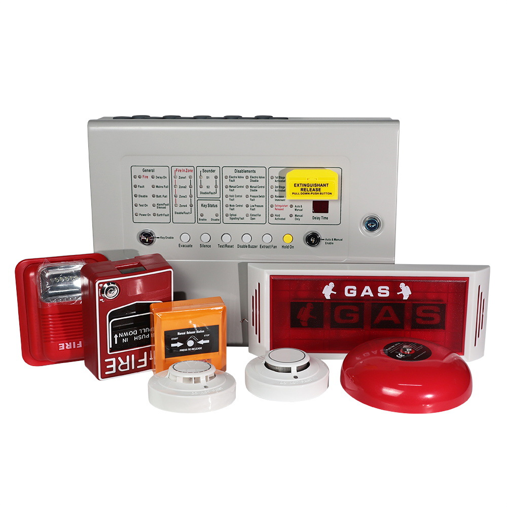
Fire fighting gas extinguish alarm panel 4 zone
The automatic extinguisher control panel is designed in accordance with European standards EN54-2 and EN54-4 Fire Detection and Fire Alarm systems - Control and Indicating Equipment and EN12094-1 Fixed firefighting systems - Components for gas extinguishing systems
Part 1:
Requirements and test methods for electrical automatic control and delay devices.
The control equipment is a combined fire alarm control panel and extinguishing
system and has four detection zones, any or all of which are capable of contributing
to the extinguisher release decision.
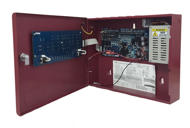
Control panels have an integral, mains powered battery charger and power supply
designed in accordance with the requirements of EN54-4.
The control equipment is a combined fire alarm control panel and extinguishing system, Delay of the actioning of fire alarm devices (sounders) so that an alarm may be verified before a premises is evacuated.
FAQ:
How is the extinguishant release activated?
There are 2 stages process and the release countdown timer.
How to prevent the gases from being vented during a discharge?
There is an extract relay.
Technical specification
Table 1 - Electrical specifications
ITEM ELECTRICAL RATING COMMENT
Size 383 mm W x 295 mm H x 87 mm D metal enclosure
Weight 5 kg
Mains supply 90 to 270VAC, 50Hz/60Hz
Mains supply fuse 3 Amp ( F3A L250V) Replace only with similar type
Power supply rating 3 Amps total including battery charge 28V +/- 2V
Maximum ripple voltage ≤200 millivolts
Battery type Two 12 Volt sealed lead acid in series. 7Ah maximum
Battery charge voltage 27.6VDC nominal
Battery charge current 0.7A maximum
Current draw in mains fail condition 0.095 Amps With buzzer sounding
Current draw in second stage alarm 0.235Amps Two zones in fire(470 ohm in circuit)
Current draw in post discharge condition 0.310Amps solenoid outputs active
Maximum current draw from batteries 3Amps With main power disconnected
NAC outputs(sounder & bell circuit) 26 to 28V DC Fused at 500mA with electronic fuse 1.2Amp total load over all circuits
Fault relay contact rating 2A /30VDC maximum for each Volt free changeover contact
Fire relay contact rating 2A /30VDC maximum for each Volt free changeover contact
First stage contact rating 2A /30VDC maximum for each Volt free changeover contact
Second stage contact rating 2A /30VDC maximum for each Volt free changeover contact
Extract contact rating 2A /30VDC maximum for each Volt free changeover contact
Zone quiescent current 4mA maximum
Terminal capacity 0.5mm2 to 2.5mm2 solid or stranded wire
Number of detectors per zone ≤30 PCS conventional detectors
Number of sounders per circuit Dependent on type and current consumption
Detection circuit end of line 4K7±5% 1/2 Watt resistor 3K-5.6K 1/2W
Monitored input end of line 4K7±5% 1/2 Watt resistor 3K-5.6K 1/2W
Sounder circuit end of line 10K±5% 1/2 Watt resistor 6.8K-20K 1/2W
Extinguishant output end of line 10K±5% 1/2 Watt resistor 6.8K-20K 1/2W
No. of detection circuits Four 21 to 28V DC
No. of sounder circuits Four 21 to 28V DC
Extinguishant release output 21V to 28V DC. Maximum load 2 Amp
Extinguishant release delay time Adjustable 0 to 75 seconds 5 second steps
SIL, AL, FLT, RST inputs Switched – min resistance 0 ohms, max 1k ohms
Detector alarm threshold 270 ohms to 1K ohms
Call point alarm threshold 150 ohms to 1K ohms
Short circuit threshold 0 ohms to 130 ohms
Status unit/Ancillary board connection Two wire RS485 connection with electronic fuse. Max. of 32 units-RS485 data cable
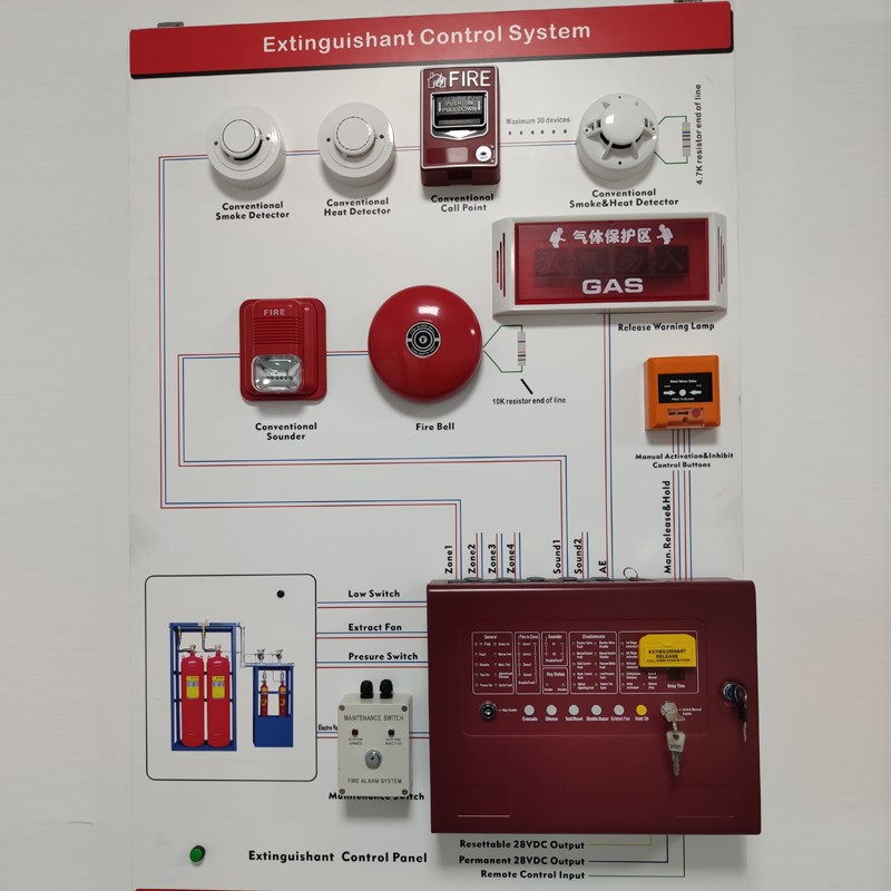
The controller is connected with Conventional Smoke Detector, heat Detector, Manual call point, on-site emergency start/stop button, aerosol extinguishing control device (or cylinder control device), weighing device, exhaust indicator light and other equipment. Constitute a complete automatic fire alarm and fire fighting system. Download manual and diagram for fire alarm and fire extinguishant system.
Conventional Fire Fighting Panel
Key Specifications/Special Features
Four Style B(Class B)Initiating Device Circuits(IDCs)。
All zones accept two-wire smoke detectors and any normally-open contact devices.
One built-in Fire Fighting Ouput.
24-volt operation.
Resettable four-wire smoke detector power@500 mA.
Non-resettable power@500 mA.
One-man walk-test programmable for silent or audible test.
Disable/Enable control per IDC.
Reverse polarity protection
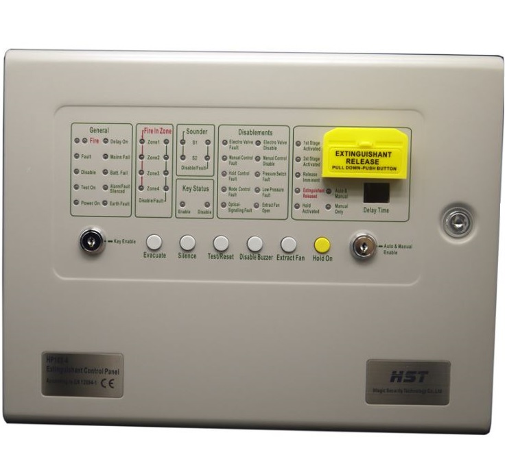
There are 6 buttons on the panel, Emergency evacuation, external muffler, Self-test/Reset, Internal muffler, exhaust fan, Emergency Stop
Control lock allows and disables key function, manual and automatic switching modes
The standby 12V/4.5A power supply is placed at the bottom of the chassis. If the battery polarity is incorrect, the yellow battery fault message is displayed on the panel.
Emergency gas release: Pull out the yellow plastic box panel on the panel, and there is a red button inside. Press the button, the controller will enter the "emergency start" delay state, showing a countdown of 10 seconds, and send a start signal after the countdown is over.
L Controller has 4 independent alarm area (ZONE1-ZONE4), can be connected with multi-line smoke, temperature, manual alarm
Button and other input equipment, can independently complete equipment fault detection and alarm function.
L The controller has three sound and light alarm outputs (SounD1-SOUND3), which can be easily used for external emergency alarm in case of fire
.
L the controller has one 24VDC/1A POWER output (power-24 v,0V) to supply POWER to external devices.
L Controller has 1 way fault, 1 way fire alarm relay output.
L The controller has remote mute, remote alarm test, remote fault test and remote reset functions.
L The controller has remote emergency start, remote emergency stop and remote hand/automatic mode switching functions.
L The controller has cylinder pressure undervoltage signal receiving function and gas release feedback signal receiving function.
L The controller has valve function.
L The controller can set 0-75s delay valve function.
L The controller has the function of manually opening and closing the exhaust fan.
L The controller has RS485 interface, which can transmit alarm information with the upper computer or the floor repeat display.
2. Technical indicators
Remarks of electrical parameters of the project
Working power supply DC12V-DC28V
Ripple voltage is 200 mV
The static current is 0.12A
The alarm current is 0.235A
The output current is 24/3a
Relay output contact capacity 24V/2A, 220V/1A
Acoustic and optical output power of each channel 24V/1A (Max)
Static currents in alarm zone (Zone1-4) 0mAminimum, 2mAmaximum
A twisted pair cable with a lead of 0.75mm2 to 2.5mm2 is recommended
The number of detectors in each alarm zone (ZONE1-4) is 25
Detector, monitor input terminal resistance 6K8±5% 1/2W
Acousto-optic alarm output terminal resistance 10K±5% 1/2W
Controller alarm area (ZONE1-ZONE4) alarm resistance 1K - 390
Parallel diodes 1N4004 or 1N4007 are recommended for valve output
Zone1-zone4: input alarm equipment for multi-wire smoke sensing, temperature sensing, manual alarm button, etc. ZONE1 and ZONE2 participate
Linkage "and" control output, ZONE3 and ZONE4 only alarm function, do not participate in linkage control output. It is recommended that ZONE1 be connected to multiple cables
- type smoke detector, ZONE2 connected with multi - line temperature detector. When both ZONE1 and ZONE2 alarm, the controller will enter the linkage loss
Out (The controller is in automatic state) state
Fire alarm and automatic fire control must be installed in communication room, warehouse, factory.