Categories
- Conventional fire alarm systems
- Wireless Fire Alarm System
- LPCB addressable fire alarm
- Gas detection alarm system
- Electrical Fire Monitoring
- Addressable fire alarm system
- Fire Alarm Fire Extinguishing
- Fire Alarm gas fire-extinguish
- Commercial Burglar Alarm System
- Security Service Equipment
- Commercial security solutions
- Industry Security Equipment
Manufacturer Info

Manufacturers
Languages
255 to 1020 point addressable fire alarm system LPCB
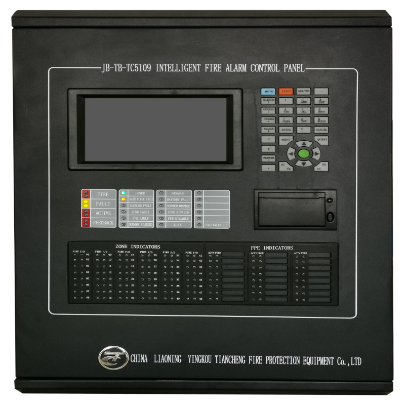

Intelligent Fire Alarm control panel LPCB fire controller 1 Loop 255points (it is also available for 2/3/4 loops).
Color menu display
Intelligent bus control mode; max 255 addressable points
per loop, max 4 loops, max 48 zones
Loop card type design:1-4 loop card can be seledted
Glass fuse per loop
Black box function
Independent controlling password for the specially needed
gas recharging units
Self-design loop protocol
Wall-mounted structure, compact and exquisite
Akzo outer coating;anti-corrosion
Language:English
Approvals:LPCB(EN54-2/4) CE
Core Functions
1. Fire Alarm Monitoring
Detect fire signals from addressable smoke/heat detectors, manual call points, and other fire-sensing devices.
Display the first/last fire alarm, zone location, device address, and time stamp in real time.
Trigger fire alarm output (HJ+/HJ–) and sounder strobe for on-site audible-visual alert.
Fault Detection & Indication
Monitor system faults: main power fault, battery fault, loop communication fault, system fault.
Monitor field device faults: detector fault, module fault, sounder strobe fault, FPE fault, zone fault.
Output fault relay signal and show fault information on LCD and LED indicators.
2. Device & Zone Management
Support up to 4 loops, max 255 addressable points per loop, total 1020 points.
Support up to 48 zones with independent fire alarm and fault/disable indicators.
Support device registration, query, definition (second code, type, attribute, location note).
Support zone/addressable point/sounder/FPE disable and enable.
Linkage Control
Automatically start/stop FPE devices (I/O modules, fire dampers, fire pumps, etc.) via logic linkage formulas.
Support linkage action and feedback signal display.
Support offline programming via USB for linkage logic and device notes.
System Operation & Control
Three-level authority control with password protection (Level I/II/III).
Functions: mute, reset, self-test, silence/resound sounder.
Multi-language switch (Chinese/English) and time/print setup.
Store up to 2000 pieces of fire alarm, fault, and event history logs.
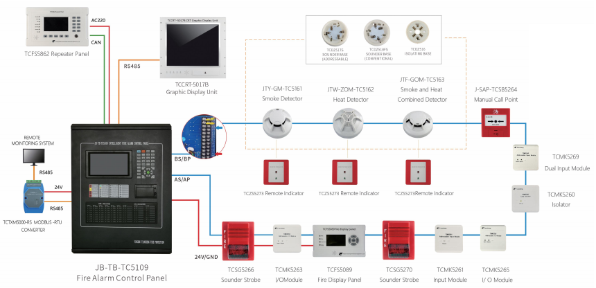
Communication & Networking
Equipped with CAN and RS485 interfaces for CRT connection and networking.
Support master/slave/stand-alone networking mode and information transmission /reception.
Power Management
Dual power supply: AC230V main power + 2×12V12AH backup battery.
Battery charge control, internal resistance detection, and fault alarm.
24V power output for field FPE and sounder strobe.
Display & Output
7-inch color LCD (800×480) for visual information display.
Built-in printer for real-time printing of fire, fault, and event records.
Multi-LED indicator panel for system status, zone status, and FPE status.
3. Installation & Maintenance
Modular plug-in structure for easy installation, commissioning, and expansion.
Loop short-circuit isolation via loop isolator to ensure system stability.
Regular test guidance and common fault troubleshooting.
TECHNICAL SPECIFICATIONS
Volate AC230V(50HZ), Voltage range: +10%--15%
Current 1A
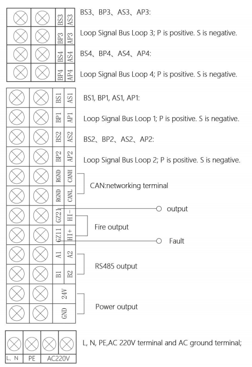
Outputs Fire output .Fault output .24V power output .Loop output
Capacity 1020/4 loops addressable points
LCD screen size 7-inch color LCD screen
Standby bettery 12V/12AH sealed lead acid battery*2
Dimension(L*W*H) 420mm×140mm×560mm
Operating environment Temperature:-5℃-+50℃: Relative Humidity:≤95%non- condensing
Communication interface RS485、CAN、USB
DETAILS
The control panel is mounted on the wall through 4 mounting holes, the dimensions of the mounting holes are shown in the picture.
The right side of the control panel has 8 wiring holes, which are easy for wiring between the control panel and field devices.
There are also 5 knock holes at the top, if the holes on the right side are not enough.
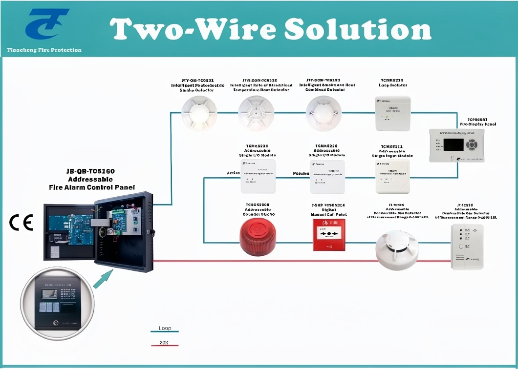
Add compatible detectors and supervisory devices at fire alarm